Scan Tool Detection
In the context on-board diagnostics (e.g., OBD-II) Wikipedia defines
"driver's supplementary vehicle instrumentation"
as:
Driver's supplementary vehicle instrumentation is instrumentation
installed in a vehicle in addition to that provided by the vehicle
manufacturer and intended for display to the driver during normal
operation. This is opposed to scanners used primarily for active fault
diagnosis, tuning, or hidden data logging.
One problem with the permanent connection of an "supplementary" OBD-II
device to a vehicle's OBD bus is what can happen when a "factory" scan
tool is connected to the bus at the same time.
Two OBD-II "scan tools" sending commands over the OBD-II bus
simultaneously may cause confusion, with OBD-II response packets from
one device being mistakenly read and processed by the other device.
In other situations, such as vehicle engine computer firmware upgrade
operations, the result can be corruption of the firmware, sometimes
requiring replacement of the engine computer.
Therefore, in situations where "supplementary vehicle instrumentation"
is "hard-wired" onto a vehicle's OBD-II bus, there needs to be some way
to disable the "supplementary" OBD-II device whenever a "factory" scan tool
is plugged into a vehicle's OBD-II connector. This is called
"scan tool detection" in the discussion which follows.
Firmware-Based Scan Tool Detection
One way to accomplish scan tool detection is to have the "supplementary"
device listen for OBD-II packets from the "factory" scan tool and then
"back off" from using the OBD-II bus while these packets are present.
Ideally, the "supplementary" device should listen for "factory" scan
tool traffic continuously. Alternatively it can listen for some time
peroid before sending OBD-II requests over the bus---for a time
period measured in seconds. This second method will tend to slow OBD-II
communications because of the increased latency.
However, this firmware-base technique is not fool-proof. In particular,
the "supplementary" device may fail to detect proprietary scan tool OBD-II
traffic on the bus and therefore fail to "back off". Also, how long the
"back off" time period should be is not obvious.
Hardware-Based Scan Tool Detection (Using a Switch)
A more fool-proof scheme for scan tool detection is based around some
sort of hardware-based scheme to detect the presence of the factory scan
tool connector. For example, a "door" with a switch might be added
to cover the vehicle's "stock" OBD-II connector. When the door is opened to
insert the factory scan tool, the "supplementary" can detect that fact
by monitoring the state of the switch.
Another "hardware option" is to replace the vehicle's OEM OBD-II connector
with a equivalent connector that includes hardware (e.g., a microswitch)
to somehow detect the presence or absense of a factory scan tool connector.
A simple microswitch built into the female OBD-II connector housing and
sensed by the "supplementary" device is one obvious option. However,
the challanges with this method include deciding exactly where to place
the switch and determining exactly what the switch should "sense".
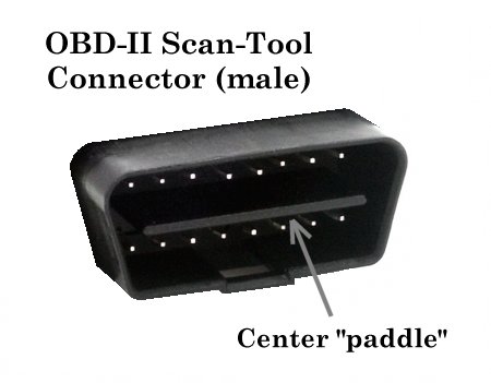 It is tempting to use a
mechanical (or optical) switch to detect the insertion of
the center alignment "paddle" specifed by the SAE OBD-II
connector standard (see figure at left). Unfortunately,
Snap-on, one of the more popular
U.S. manufacturer of scan tools used by independent automotive repair
shops, does not include a center "paddle" with their scan tools' OBD-II
connector. It is tempting to use a
mechanical (or optical) switch to detect the insertion of
the center alignment "paddle" specifed by the SAE OBD-II
connector standard (see figure at left). Unfortunately,
Snap-on, one of the more popular
U.S. manufacturer of scan tools used by independent automotive repair
shops, does not include a center "paddle" with their scan tools' OBD-II
connector.
Another challenge when positioning some sort of scan tool detection switch
in the "vehicle" OBD-II connector is the fact that practical realities of
OBD-II connector "geometry" are such that scan tools tend to operate just
fine with a partially inserted OBD-II connector. Any switching scheme
embedded in the vehicle's OBD-II connector needs to deal with this fact.
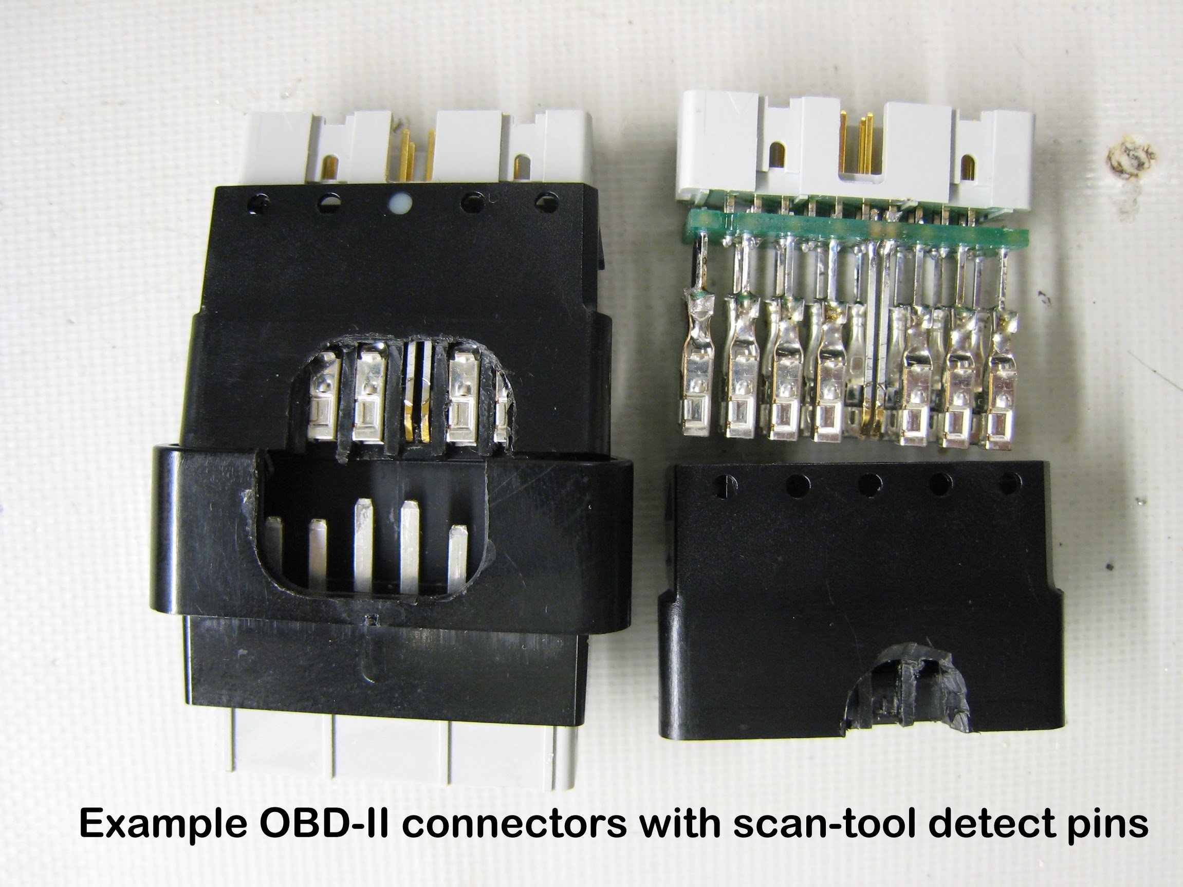
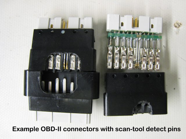
Hardware-Based Scan Tool Detection (Detecting Ground Pin)
 The following describes a novel and virtually fool-proof way of detecting
the presence of a scan tool connector. Instead of detecting the physical
presence of the scan tool's OBD-II connector housing, this method detects
the presence of the scan tool's OBD-II "ground" pin.
The following describes a novel and virtually fool-proof way of detecting
the presence of a scan tool connector. Instead of detecting the physical
presence of the scan tool's OBD-II connector housing, this method detects
the presence of the scan tool's OBD-II "ground" pin.
Given that a ground connection is required for the scan tool electronics
to operate properly, somehow detecting that this connection has been
made offers an ideal way of detecting the presence or absense of a scan
tool device.
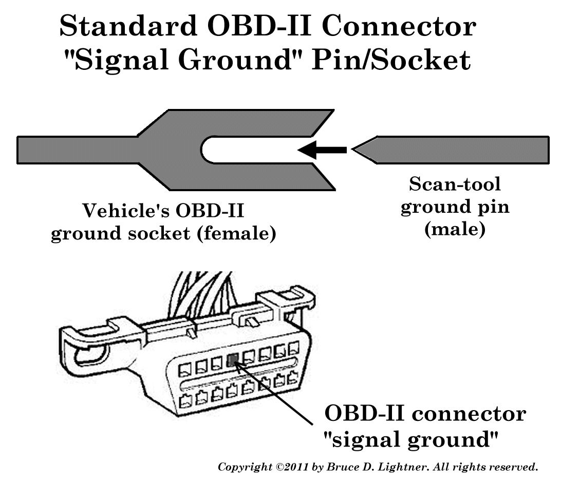
The figure on the right shows the mechanics of a typical OBD-II
connector pin and socket connection. The female "sockets" built into
in a vehicle's standard 16-pin OBD-II connector receives the male "pins"
built into the scan tool's mating OBD-II connector. The "signal ground"
(i.e., OBD-II connector pin 4) highlighted in the figure.
Note that the ground pin(s) in the scan tool connector are slightly longer
than the other connector pins, to ensure that a solid ground connection
is made first, whenever the connector is inserted.
 The next figure shows how a vehicle's "standard" female OBD-II can be
replaced with a specially "modified" OBD-II connector, with the normal
"signal ground" contact assembly being replaced with a dual-contact
assemably.
The next figure shows how a vehicle's "standard" female OBD-II can be
replaced with a specially "modified" OBD-II connector, with the normal
"signal ground" contact assembly being replaced with a dual-contact
assemably.
Where there was a single "ground" contact there are now
two contacts, arranaged such that the insertion of the scan tool pin
will short both contacts together, as well as making contact between the
vehicle and scan tool ground pins. Note that when no scan tool "ground"
pin is present, the two contacts on the "vehicle side" are isolated from
each other.
As indicated in the figure, inserting scan tool's ground pin not only
connects the scan tool ground to the "supplementary" OBD-II device ground,
but also shorts the "scan tool detect" signal to ground. Note also, that
given that the "supplementary" device ground is connected to the vehicle's
OBD-II bus ground, the scan tool also will be connected to vehicle ground.
By connecting a "pull-up" resistor between the "scan tool detect"
contact and a bias voltage (e.g., +5V), the "supplementary" device can
readily sense then insertion of the scan tool ground pin using a digital
(or analog) input pin. Therefore, whenever a scan tool is connected
the "scan tool detect" signal will change state from the pull-up bias
voltage to ground.
Because the scan tool's male OBD-II connector pin(s) are longer then the
other bus signal pins, this scheme works will work with partially
inserted OBD-II scan tool connectors. This is because the scan tool
will not function properly unless the ground connection is completed,
and when completed the "supplementary" OBD-II device therefore will
detect the scan tool's presence.
Note that using the above described "dual contact" pin assembly
with a simple OBD-II connector (i.e., "signal ground") should
be sufficient to detect virtually all scan tools. However, to be
absolutely certain that this scan tool detection scheme works with all
possible scan tool grounding configurations, both OBD-II connector
ground pins should employ the "dual contact" pin assembly---namely
"signal ground" (pin 4) and "chassis ground" (pin 5).
If both OBD-II ground-pins use this scheme then only a single "scan
tool detect" input is needed in the "supplementary" OBD-II device.
This is because both "dual contact" pin assemblies can share the same
"detect" signal input.
Copyright ©2011 by Bruce D. Lightner. All rights reserved.
Last updated
Tue Aug 24 08:24:42 PDT 2021

Home
|